Gaugette

a simple and cheap Arduino analog gauge using the Switec X25.168 stepper motor.

Well Ain’t That Shiny!

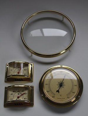
I’ve been looking around on-line and in stores for some parts to make some classy steam-punk gauges. After a lot of searching I came across Lets Make Time here in Australia who carry clock and weather station parts at very reasonable prices. It’s always hard to gauge build quality from pictures, so I laid down some cash and bought a grab bag of stuff.

The order arrived and it all looks great. It was no surprise to find the rectangular gauges are made from plastic and look a bit cheap, but I really love the retro shape and they actually don’t look too bad. I haven’t cut one open yet, but from the outside everything looks great for my purposes.

The large lens is glass, with a metal rim, mounted over a plastic frame. I’m very pleased with it too.

The circular thermometers turned out to be the real gem in this collection. The outer ring is metal, and the lens is acrylic but well finished and looks beautiful. The printed dial seems to be made out of metal too - maybe aluminium with a gold-coloured foil on both sides. As an extra-happy bonus, the needle fits the shaft of the X25s so it can be used with no modification.

A Simplified Acceleration Model

The logic in the advance() function of the Switec X25 library steps the motor forward or backward one step, then computes the delay in microseconds until the next step is due. This logic determines the acceleration curve and maximum speed of the needle. My first cut at this code used floating point arithmetic to model this as time/accel/velocity problem. The motion was nice and smooth, but it was overkill, and consumes too many precious Arduino compute cycles. When driving multiple motors, this will create an artificial ceiling on the maximum motor speed.

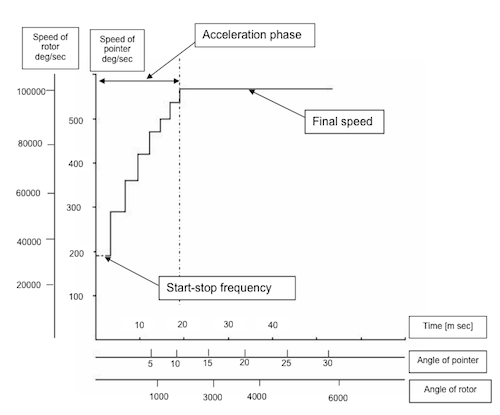
I’ve rewritten that logic to use a simple lookup table instead. This is a fairly obvious approach, but it was reassuring to see similar approaches recommended in both the VID 29 documentation and the MCR MR1107 data sheet.

The acceleration curve is defined as pairs of vel,delay values:

unsigned short accelTable[][2] = {
  {   10, 5000},
  {   30, 1500},
  {  100, 1000},
  {  150,  800},
  {  300,  600}
};

We maintain a variable vel (which isn’t actually velocity, but is a surrogate for velocity) that increments each step under acceleration, and decrements each step under deceleration. When stationary, vel is zero. After 1 step of acceleration it is 1. For simplicity I’ve made the acceleration and deceleration curves identical so they can share the same lookup table.

To determine the inter-step delay at any given value of vel, we find the first table entry such that accelTable[i][0] < vel. In practice this means that the motor will step at 5000 µS intervals for 9 steps, then 1500 µS steps for the next 20 steps, 1000 µS for the next 70 steps, and so on. The peak speed with a delay of 600 µS equates to 1666 Hz step rate or about 500 degrees per second.

The motion control logic first determines if the motor is subject to acceleration, at full speed, or deceleration and adjusts vel accordingly. Using steps as the unit for vel makes it very easy to determine when to declerate: when vel is greater than or equal to the number of steps to reach our destination, we need to start decelerating.
The new logic also ensures that if the motor is moving at speed in one direction and is directed to a new position in the opposite direction it will decelerate to a stop before accelerating in the opposite direction.

The constants that make up the acceleration table are constrained by the the inertia of the needle attached to the motor. The VID 29 documentation gives some recommendations for calculating these values, but I actually didn’t use that. I experimented until I found values that were within operational limits and look nice to me.

I tested this code driving 3 motors simultaneously with an Arduino Uno. All good. New code is in the library on Github.
Attack of the Switec Clones?

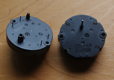
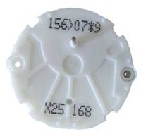
When my eBay Switec X25.168 motors arrived, they didn’t look at all like the white motors with the “Switec” branding that I’ve been seeing online. I finally got around to tracking down what exactly they are. They have two identification numbers printed black on black: vid29-02p and d11455db.

It turns out that the first number is the model, and these are in reality VID29 series stepper motors from Hong Kong VID. Interestingly their data sheet includes details of recommended acceleration characteristics to bring the motors to full speed without visible and audible jitter. Cool cool cool.

Armed with that information I turned up what appears to be a third manufacturer, MCR Motor who call this motor the MR1108. The MCR data sheet lists the Switec and VID motors as alternatives.

The eBay seller had these marked unambiguously as X25.168 motors in their auction, but didn’t specifically say they were from Switec. I wonder if any of the eBay offers are actual Switec motors?

Two Motors, One Arduino

Last night I built a pair of improved wiring harnesses so I could connect two motors to the Arduino. Once concern I have is that the control logic that manages the acceleration and deceleration could be so slow that it will interfere with the motor drive signaling when trying to control more than one motor. I have in mind to replace the floating point logic with a lookup table, but for now I like being able to easily fiddle with the motion parameters.

It turns out that two motors work pretty well with only minor tweaks to the existing code.

X12 Quad Driver Chip

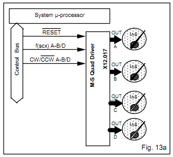
The X25 data sheet describes the X12 family of driver chips which allow up to 4 Switec motors to be controlled over a 3-wire serial interface. I like the look of these for keeping the I/O count down, and offloading a bunch of processing from the Arduino.

However I have been unable to find a supplier for X12 quad driver chips. It seems that they were available until recently from Swatch subsidiary Microcomponents Ltd. at microcomponents.ch, but after Swatch sold the stepping motor business to Singapore-based Juken Techonology in 2009, that website disappeared.

Motor Acceleration and Deceleration

My first cut at the Switec X25 library stepped the needle at a constant speed. You can see the constant speed motion in the original video.

I’ve updated the library to support acceleration and deceleration, partly because it seems more aesthetically pleasing, and partly because I have a notion that I should be able to reach faster peak speeds by ramping the speed up. Motion is now specified by 4 parameters: minimum speed, maximum speed, acceleration, deceleration.

For now I’ve used floating point calculations to compute each step period standard Newtonian velocity/distance/time calculations. This works okay, but is unnecessarily compute-intensive.

The Switec X25 library supports multiple motors and no doubt this computation will become a factor when I try to drive more than one motor, so I’ll have to address that at some point.

One interesting aspect of the control logic is that the calculations are done at the start of each step, in distance-domain rather than in time domain like most simulations. This means the calculations must be done more frequently at higher needle speeds. This is going to set an upper bound on maximum step rate.

When it does become an issue, I think I could replace the entire floating point calculation with a small table of pre-computed (step-count, step-period) pairs with little perceptible difference.

Initial Results

Wiring It Up

Given the comments by Toby Catlin about cooking the motors while soldering, I opted to make up a harness with a connector rather than soldering directly to the motor. The pins on each winding exactly match the spacing of the first and fourth pins of a standard 0.1” connector. JST RE connectors are the right pitch, but the pins on the motor are too short and too narrow to engage with the connectors. For my first harness I cut up a floppy disk cable connector into two 4-hole sections and soldered wire to the first and fourth pins. It worked fine but it is pretty bulky, and the metal contacts in the connector did not solder very easily. For now I just pushed the tinned ends of the wires directly into the Arduino connectors.

I wrote some code for the Arduino to step the motor using the IO pattern established in this post and a quick ruby script to query my pfSense firewall to get some live data to test with.

Add some duct tape for a gauge, and behold the simplest analog bandwidth meter ever:

What Is Gaugette?

Gaugette is a project detailing the construction of custom analog gauges using an Arduino microcontroller and Switec X25.168 stepper motors. Each motor requires 4 digital I/O pins, and a single Arduino can drive three motors. The limit is purely due to Aruidno limit of 14 digital I/O lines.

Source code for the project is available on GitHub.

Motivation

After playing with the motor shield party pack from Adafruit, I started thinking it would be fun to have a couple of analog gauges mounted on the wall somewhere to show system health indication; maybe network bandwidth or web traffic? Of course I’ve seen the very beautiful TorrentMeter by Skytee which is so pretty it makes me weep, but beautiful brass antique voltmeters are in short supply around here.
The servos and steppers in the Adafruit pack aren’t ideal for driving gauges. The little stepper they include runs really hot. The servo seemed like possibility and it is driven by PWM, so I wouldn’t even need the motor shield. But it is quite bulky and noisy, so I started looking for something better.

The Switec X25 Stepper Motor

I noticed a lot of sellers on eBay selling tiny Switec X25 motors as replacements for GM auto instrument clusters. They were developed by the technology arm of Swatch, so I figured they should be low power and pretty quiet. Certainly they are cheap; under $5 each!

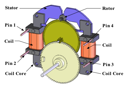
The X25 motors have 6 steps per revolution, and a 180:1 gearbox, giving a resolution of 1/3 degree. The data sheet indicates they draw no more than 20mA per winding, which is low enough to source directly from the 5V Arduino data pins, raising the possibility of driving these without an intermediate controller chip. Yes, I understand the risks associated with wiring inductive loads directly to the microcontroller. Arduinos are cheap, why not try it?

On the net I found an excellent overview of the Switec X25 by Mike Powell. Mike expresses concerns about driving inductive loads directly from the microcontroller and uses an external L293D driver. There is an intriguing thread by Toby Catlin which approaches the issue of driving these without a controller, but the thread ends abruptly at the point where he sees the first signs of success. What happens next? Blue smoke?

At the price I figured it was worth a shot driving these directly, so I ordered 6 from one of many eBay stores selling them. Apparently a complete GM instrument cluster has 6 motors, so 6 is a popular quantity. In all it cost about $25 including postage from the US to Australia. At the time of writing they carry both the X25.168 with rear contacts, and the X25.589 with front contacts and a longer indicator shaft. Both have internal stops. See the buyers guide for details on the different models.