Gaugette

a simple and cheap Arduino analog gauge using the Switec X25.168 stepper motor.

Buyers Guide

Manufacturers

I am aware of three companies manufacturing compatible motors. All appear to produce a good-quality product.

Switec

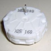
Switec was originally the technology arm of the Swiss watch company Swatch. The stepper business was sold off to Singapore-based Juken Technology in 2009. Switec motors are white, and have part numbers starting with “X”.

VID

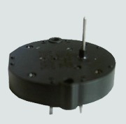
Hong Kong based VID also manufacture a range of similar motors. Their motors are black, and have a black model number starting with “vid”.

MCR

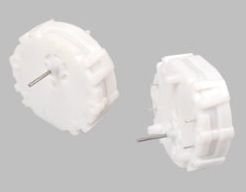
Chinese company MCR Motor manufacture a range of compatible motors. Their motors are white. with part numbers starting with “MR”.

X25 Product Numbers

Each manufacturer produces a number of variations of the motor.

SwitecVIDMCRContactsMounting PegsInternal StopShaft
X25.156rearnonostandard
X25.166rearnoyesstandard
X25.158rearrearnostandard
X25.168VID29-02MR1108rearrearyesstandard
X25.278rearrearnolong (+2mm)
X25.288VID29-04rearrearyeslong (+2mm)
X25.559frontfrontnostandard
X25.569VID29-05MR1107frontfrontyesstandard
X25.579frontfrontnolong (+2mm)
X25.589VID29-07frontfrontyeslong (+2mm)
X25.679frontfrontnolong (+2mm)
X25.689frontfrontyeslong (+2mm)

Other Switec Series

X23 Series

The X23 motors have an a hollow metal shaft encasing a transparent light guide to make it possible to have an illuminated pointer.

X26 Series

The X26 motors are dual-shaft analog clock motors. The model numbers are X26.101, X26.103, X26.123, X26.504. See the the “Switec Series Buyers Guide” in the Resources for more details.

X27 Series

The X27 motors are a new line replacing the X25 series. The X27 part numbers mirror the X25 series.

X12 Motor Drivers

The X12 part numbers refer to a series of driver chips developed by Switec. I have not been able to locate a supplier of these chips since microcomponents.ch shut down.

Suppliers

I have not found any well-know online store supplying these parts. They are however cheap and plentiful on ebay. However it can be difficult to determine exactly what you are getting; these motors are generally sold as Switec X25 replacements, without clearly specifying the manufacturer.

How Fast Is It?

I recently removed the internal stops on a VID-29 stepper. I’ve used this free-turning motor and an optical sensor to exerimentally test some operational limits of the motor. The test rig uses a photo-interruptor to determine the needle position:

Methodology

I move the need forward under varying conditions, then move the needle back to the home position in a known-reliable manner while counting the steps. If the steps counted back do not match the number of steps programmed forward then we know we have exceeded the operational limits of the motor.

After some experimentation I selected a delay of 1000μS per step for the counting phase as this is well within the safe limits of operation. I confirmed that in this safe range I get reliable results counting steps confirming that the sensor is accurate enough to detect a single one-third degree step.

Note: Be sure your needle is tight! Until I eliminated needle slippage, my results showed anomalous drifts both above and below the expected values.

Constant Speed Test

In this test the motor is turned at constant speed to identify the maximum constant speed that the motor will respond to. The speed is set by manipulating the motor accelleration table. I also recorded the total sweep time with the micros() function to determine the variation between the programmed inter-step time and the actual inter-step time.

The following table shows the results from the constant speed test. Each test was repeated 5 times. In each case the expected result was 500.

Delay μSTest 1Test 2Test 3Test 4Test 5Actual μSSteps/Sec°/S
5004-64-645091964654
5204-64-645301886628
5402-42-425491821607
5602-42-555681760586
5802-42-425891697565
600927-426101639546
620500506500926301587529
6405005005005005006491540513
6605005005005005006681497499
6805005005005005006911447482
7005005005005005007111406468
7205005005005005007291371457
7405005005005005007491335445
7605005005005005007711297432
7805005005005005007911264421
8005005005005005008101234411

Results

The results show that with a programmed step period 600μS or less the motor could not advance with each step - and in fact often moved backwards. At 620μS the results were unreliable, and at 640μS and above the motor behaved reliably.

The actual inter-step delay was 8 to 11 μS more than the programmed delay.

Observations

I compared my results with the VID29 data sheet which states rather confusingly that “The angular speed can reach more than 500Hz” (presumably they mean °/S, not Hz?), and elsewhere that the maximum driving frequency is 600Hz (I can’t make any sense of that). The ~10μS difference between programmed delay and measured delay gives a useful measure of the error of the timing logic in the SwitecX25 library.

In setting up this test I discovered a bug in the SwitecX25 library: the library does not enforce a timing delay between the last signal change before stopping, and the first signal change after starting. This only exhibits if the motor is stopped and immediately restarted (within ~600μS). Because the two signals come too close together, the step may be missed. This leaves the motor out of phase with the libraries state map, and it appears the motor then misses 5 more steps before it gets back into phase, so this error shows as a 6-step error.

Test Code

Here’s the full source code for this test.

Making Wiring Harnesses

A quick note about wiring harnesses for these motors. I’ve found it really handy to make harnesses from 4-wire CD audio cables. My harnesses use push-on connectors at the motor end so I never accidentally cook the motor by soldering to the motor pins.

image

The cables I’m talking about have 4-pin JST connectors on each end, and are used to connect the analog audio signal from a PC’s internal CD player to the motherboard or sound card. I have accumulated a bunch of these over the years, so I’m glad to have a use for them.

I also use 0.1” breakaway headers and heatshrink tubing, both from AdaFruit.

image

  • Chop the audio cable in half (each half makes one wiring harness),
  • Strip and tin the wires on the cut end,
  • Cut off a 4-pin section of breakaway header,
  • Solder the wires to the header with the two black wires in the center positions,
  • Protect the connections with heat-shrink tubing.

image

  • Pull up the plastic tabs on the JST connector and slide the crimped terminator out of the block,
  • Use pliers to close the crimp connectors a little, but don’t crush them entirely. The pins on the Switec motors are really small, so you need to squeeze it down a little to create a tight fit.

image

You’ll notice that these harnesses have two black wires, which would normally be a bit annoying. However it turns out that the wires to pins 2 and 3 on the Switec motors are interchangable so you don’t need to distinguish between them.

Wire your motor up like this:

Motor PinWire ColorArduino Pin
1white4
2black5
3black6
4red7

Be careful not to bend the pins on the motors when you slide the crimp connectors on. Also note that the pins on the motor are flat, not round, so the orientation of the crimp connector matters; if it is too tight or too lose, try rotating the connector 90 degrees.

Finally, if you plug the header into an Arduino so that white is at pin 4, and red is pin 7, you can define your motor in code like this:

1
SwitecX25 motor1(MOTOR_STEPS, 4,5,6,7);

Pulling Out All the Stops

Or more accurately, filing off the stops.

Recently Tim Hirzel asked if I knew of a source of motors without stops, or if the X25.168’s could be modified to remove the stops and open up the full 360 degrees of rotation.

Good question! The X25 Series Buyers Guide lists 6 models of motors without stops, but a quick search turned up no suppliers selling these in small volumes.

Okay, time to figure out if the stops can be removed. Note that I’m working on a VID-29 clone, not a genuine Switec X25.168 here. There are 4 tiny screws that open the case revealing this:

image

The drive-shaft and attached gear sit loose and can be lifted out. Flipping the gear over reveals the mechanism for the stop; a raised trapezoidal bump on the gear face that stops against a matching protrusion at the bottom of the case.

image

I cut off the stop with a Stanley knife, and filed it flat with a small file.

image

Reassembly was easy, and bugger me, it works.

In the video you can see the needle hesitates on each rotation. This is because of the acceleration/deceleration logic in the SwitecX25 library; I’m accelerating the motor from stop, spinning 360 degrees, decelerating to a stop again, then repeating, using code like this:

1
2
3
4
5
      for (int i=0;i<nLoops;i++) {
        motor->currentStep = 0;    
        motor->setPosition(360*3);
        while (!motor->stopped) motor->update();
      }

To keep the speed constant I need to prevent it coming to a stop. I can do that by resetting the origin and destination before it reaches its goal step, like this:

1
2
3
4
5
      for (int i=0;i<nLoops;i++) {
        motor->currentStep = 0;         // reset origin on each rotation 
        motor->setPosition(320*3*2);    // set target to way past end of rotation
        while (motor->currentStep<360*3) motor->update();  // turn until rotation is complete
      }

Or to run the motor in reverse:

1
2
3
4
5
      for (int i=0;i<nLoops;i++) {
        motor->currentStep = 360*3*2;
        motor->setPosition(0);
        while (motor->currentStep>360*3) motor->update();
      }

I think the SwitecX25 library will need some extensions to support stop-less motors… need to think about that a bit.

A Better Backlight

For the second gauge in this build, I tried to get better placement of the current-limiting resistor. By placing it tight in the corner, it wont cast a shadow.

These photos show the LEDs at 100% brightness, but they are on PWM pins so I can control the intensity from the Arduino code.

It is subtle, but in the next photo you can see the difference between the first and second gauge. The right-most gauge has a dark spot between 30 and 40. It’s fine, and the light spread isn’t that even anyway, so I’m going to call it ‘character’.

The mounting panel is made from salvaged hardwood fence pickets. It’s red stringybark, very hard and with nice colour and grain definition.

I’ve wired the 3-position switch to control “off”, “on” and “on with backlight”.

Using the SwitecX25 Library

Getting Started with the SwitecX25 Library

For Arduino IDE version 1.0 and later you can store user-contributed libraries in a subdirectory of your sketch directory named ‘libraries’. In fact you really should install them there to ensure that they persist when you upgrade the IDE.

So figure out where your project directory is (under OSX this is available in the Arduino -> Preferences menu), create a subdirectory called libraries with the project directory. The name is important, so use exactly that. Then inside that libraries directory checkout the SwitecX25 library. You should end up with this structure:

1
2
3
4
5
6
libraries
  |
  +-- SwitecX25
     |
     +-- SwitecX25.cpp
         SwitecX25.h

There is also an examples directory under that, but those two files are the critical parts of the library.

Restart the IDE and you should see the library in your Sketch -> Import Library menu. It appears in a separate section at the bottom marked contributed. Now start a new sketch. Here’s a minimum Hello World sketch for the Switec X25 that runs the motor against the zero stop then moves the motor to the center of its range.

1
2
3
4
5
6
7
8
9
10
11
12
13
14
15
16
17
18
19
20
21
#include <SwitecX25.h>

// standard X25.168 range 315 degrees at 1/3 degree steps
#define STEPS (315*3)

// For motors connected to pins 3,4,5,6
SwitecX25 motor1(STEPS,3,4,5,6);

void setup(void)
{
  // run the motor against the stops
  motor1.zero();
  // start moving towards the center of the range
  motor1.setPosition(STEPS/2);
}

void loop(void)
{
  // the motor only moves when you call update
  motor1.update();
}

I’ve added this little sketch to the library as an example, so it will appear as File -> Examples -> SwitecX25 -> center.

LED Gauge Backlighting

Today I added an LED backlight to my square gauge. I really like how light leaks from the grills at the top and bottom of gauge.

I decided not to use RGB LEDs in this build due to size and pin-count constraints. The white LED was originally part of a solar-powered LED light string.

These are side-emitting LEDs by virtue of a conical indent in the tip of the lens that refracts much of the light sideways. I tried grinding back the lens and using blobs of hot-glue to make the lighting more diffuse, but in the end I wasn’t convinced it was an improvement, and so the simpler design won out.

I soldered the 330Ω current-limiting resistor to the LED. I trimmed the leads on the LED and resistor really short to get it all to fit. I would have liked the resistor tight against the wall to prevent a dark spot, but it didn’t work out that way.

The holes for the connection wires had to be drilled right in the extreme inner corner to avoid the stepper motor on the back. The cathode wire goes to a PWM pin on the Arduino, and the anode to ground. I recently added LED control options to the Gaugette software to control the brightness.

ZOMG, now this gauge totally looks like the helmets worn by the Viper pilots in the original 80’s Battlestar Galactica series!

Just a Pretty Face

I made dial faces for a couple of the square gauges built in Build Number One. Nearly ready to install these guys.

Laying out the line-work on the square faces presents an interesting challenge. I decided to generate the bare line-work programmatically with a ruby script, and add the labels later with a graphics tool.

My first attempt at the script used the GD2 library, but GD2 doesn’t seem to support anti-aliasing or line-caps and the resulting line-work was just too damned ugly. I switched to Cairo which makes pretty, pretty lines. A revelation at this point was that I could use Cairo’s clipping operator to trim the graticule lines and remove the messy trig I was coding to figure out line intersections and stroke lengths. Finally I imported the generated image into OpenOffice to add the text labels.

So what to print on? On a recent trip to Cairns I looked in Officeworks for ideas. I didn’t find any card stock I liked, but I did find some 120 gsm paper (Quill brand “Metallique” in Mother of Pearl) with a cool metallic / opalesque finish. 120 gsm is heavier than standard typing paper, and maybe barely stiff enough to support itself in the gauge. Over time it might curl or slump in the varying humidity here in the tropics. There is just enough drive shaft length to place the paper over the original dial plate so that the needle just clears the face, but if the paper will support itself I could backlight it with an LED which might look nice in the dark.

One thing that had me stuffed is how to punch a neat hole in the paper for the drive shaft. A standard hole-punch is too big and can’t reach far enough from the edge of the paper. Drilling would leave messy edges. Scouring the aisles at Officeworks I found a set of three eyelet setters from Fiskars in the scrap-booking section. The hole punches use a crazy spring-driven hammer mechanism, so you can position them anywhere on the page, pull back the hammer, and smack, you have a hole. I was reckon I want a 3mm hole, and the middle size is 3.2mm (1/8”). The downside is the set of 3 cost about $25. Anyway they work a treat and now I have some crafty hole punches.

I tried printing the dials with an ink-jet. That seemed okay until I mounted it in the gauge and I found that at certain angles the metallic finish on the paper made the line-work look really washed out. Redoing the printing with a laser printer gave much better results.

After installing the new face I calibrated it carefully and found a discrepancy between the printed face and needle position that I can’t explain. If I line up zero precisely, then at full-scale (230 degrees sweep) I find the needle is about 2 degrees short of the 100% mark on the dial. I’m not sure what the source of error is - presumably just measurement and positioning errors - but it is easily solved by changing the stepper motor sweep from 690 steps to 696 steps to full-scale deflection.

Separation Anxiety

I’ve separated the Switec X25 motor driver code into a separate library repository on GitHub. This will make it easier to use the driver library in other applications.

SwitecX25 Library

This contains only the Switec X25 driver.

Gaugette

This is an arduino application that controls analog gauges by interpreting commands received over the serial interface. To compile Gaugette you will now need to add the SwitecX25 library to your Arduino libraries folder.

Gauge Build Number One

This weekend I opened up one of the cheap-but-funky thermometers/hygrometers from Lets Make Time and replaced the thermometer mechanism with the Arduino-controlled Switec X25.168 stepper.

The thermometer and hygrometer are installed in identical one-part plastic housings with no screws or seams, so it wasn’t clear how to crack them open. 
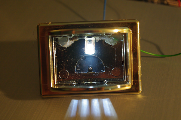
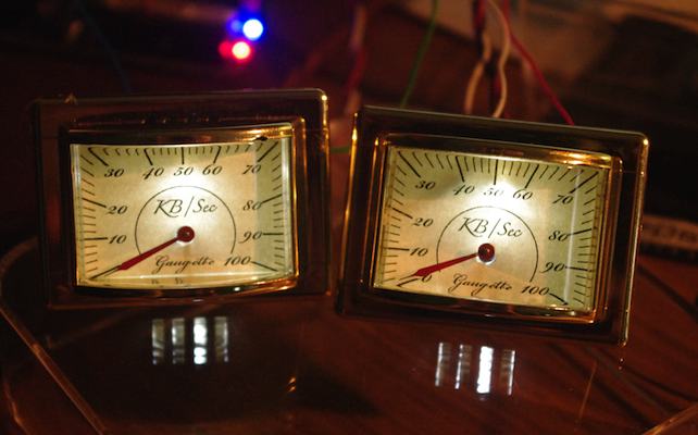
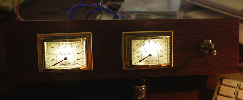
I used a Dremel to cut away the back panel giving access to the thermometer mechanism, but to my surprise the dial face was still firmly locked in place. After a bit of poking around I discovered that I could push the whole assembly out forward - in fact the plastic lens is only held in by friction, and the dial and mechanism are held in by the lens. No cutting was required. #LFMF

This turned out to be important because after careful measurement I realized that the motor would have to be mounted snugly against the the back of the housing to leave the drive shaft protruding enough to attach a needle. The plastic panel I cut away would have been ideal to screw the motor to. Starting again with an undamaged housing, I gently pried out the plastic lens, removed the face and mechanism. This time I only cut away enough plastic on the back to allow the drive shaft to pass through.

The needle and the bi-metal thermometer coil came off the face easily enough, but the mounting for the coil is a crafty two-piece deal that mounts through the centre of the dial. It appeared to be assembled a bit like a rivet, and a couple of solid blows from the back with a punch released it cleanly from the dial face.

I originally intended to use screws to secure the stepper to the back of the housing, but there isn’t much tolerance for positional error, which made me nervous. Instead I used the conical rivet-thingy to precisely align the motor drive shaft in hole in the dial and held it all in place while I hot-glued it to the back of the case. Alignment was spot-on the the motor seems to be solidly secured. So far so good.

Next I wired up the Arduino and zeroed the motor against the low stop and put the needle on. There were some unexpected complications at this point. The motor has a sweep of 315 degrees, but this dial only allows about 230 degrees of needle movement. I modified the library to support a soft range limit to avoid exceeding 230 degrees, while still running through a full 315 degrees during reset.

While trying to calibrate the dial I found the needle slipping at times, especially under vibration caused by the power-on reset or slow stepping. With the needle slipping calibration was impossible. I tried applying the smallest drop of hot glue I could manage to the back of the needle. That really didn’t work - the tiny irregular mass between the needle and the dial face would sometimes bind against the dial face, causing more problems.

I believe the needle hole is dished a little, so I removed the needle, cleaned the glue away, and smacked it with a hammer to flatten out the dish and close up the hole. That worked a little too well and I had to ream the hole out a bit with a thumb tack. Now the needle is nice and snug, no slippage.

So here’s how it looks assembled. Calibration is slightly out, but I’m going to make a new dial face anyway, so no need to sweat about that.