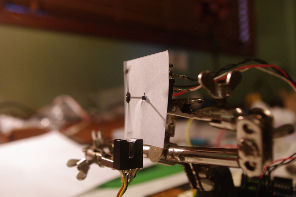
I recently removed the internal stops on a VID-29 stepper. I’ve used this free-turning motor and an optical sensor to exerimentally test some operational limits of the motor. The test rig uses a photo-interruptor to determine the needle position:
Methodology
I move the need forward under varying conditions, then move the needle back to the home position in a known-reliable manner while counting the steps. If the steps counted back do not match the number of steps programmed forward then we know we have exceeded the operational limits of the motor.
After some experimentation I selected a delay of 1000μS per step for the counting phase as this is well within the safe limits of operation. I confirmed that in this safe range I get reliable results counting steps confirming that the sensor is accurate enough to detect a single one-third degree step.
Note: Be sure your needle is tight! Until I eliminated needle slippage, my results showed anomalous drifts both above and below the expected values.
Constant Speed Test
In this test the motor is turned at constant speed to identify the maximum constant speed that the motor will respond to. The speed is set by manipulating the motor accelleration table. I also recorded the total sweep time with the micros() function to determine the variation between the programmed inter-step time and the actual inter-step time.
The following table shows the results from the constant speed test. Each test was repeated 5 times. In each case the expected result was 500.
| Delay μS | Test 1 | Test 2 | Test 3 | Test 4 | Test 5 | Actual μS | Steps/Sec | °/S |
|---|---|---|---|---|---|---|---|---|
| 500 | 4 | -6 | 4 | -6 | 4 | 509 | 1964 | 654 |
| 520 | 4 | -6 | 4 | -6 | 4 | 530 | 1886 | 628 |
| 540 | 2 | -4 | 2 | -4 | 2 | 549 | 1821 | 607 |
| 560 | 2 | -4 | 2 | -5 | 5 | 568 | 1760 | 586 |
| 580 | 2 | -4 | 2 | -4 | 2 | 589 | 1697 | 565 |
| 600 | 9 | 2 | 7 | -4 | 2 | 610 | 1639 | 546 |
| 620 | 500 | 506 | 500 | 9 | 2 | 630 | 1587 | 529 |
| 640 | 500 | 500 | 500 | 500 | 500 | 649 | 1540 | 513 |
| 660 | 500 | 500 | 500 | 500 | 500 | 668 | 1497 | 499 |
| 680 | 500 | 500 | 500 | 500 | 500 | 691 | 1447 | 482 |
| 700 | 500 | 500 | 500 | 500 | 500 | 711 | 1406 | 468 |
| 720 | 500 | 500 | 500 | 500 | 500 | 729 | 1371 | 457 |
| 740 | 500 | 500 | 500 | 500 | 500 | 749 | 1335 | 445 |
| 760 | 500 | 500 | 500 | 500 | 500 | 771 | 1297 | 432 |
| 780 | 500 | 500 | 500 | 500 | 500 | 791 | 1264 | 421 |
| 800 | 500 | 500 | 500 | 500 | 500 | 810 | 1234 | 411 |
Results
The results show that with a programmed step period 600μS or less the motor could not advance with each step - and in fact often moved backwards. At 620μS the results were unreliable, and at 640μS and above the motor behaved reliably.
The actual inter-step delay was 8 to 11 μS more than the programmed delay.
Observations
I compared my results with the VID29 data sheet which states rather confusingly that “The angular speed can reach more than 500Hz” (presumably they mean °/S, not Hz?), and elsewhere that the maximum driving frequency is 600Hz (I can’t make any sense of that). The ~10μS difference between programmed delay and measured delay gives a useful measure of the error of the timing logic in the SwitecX25 library.
In setting up this test I discovered a bug in the SwitecX25 library: the library does not enforce a timing delay between the last signal change before stopping, and the first signal change after starting. This only exhibits if the motor is stopped and immediately restarted (within ~600μS). Because the two signals come too close together, the step may be missed. This leaves the motor out of phase with the libraries state map, and it appears the motor then misses 5 more steps before it gets back into phase, so this error shows as a 6-step error.
Test Code
Here’s the full source code for this test.